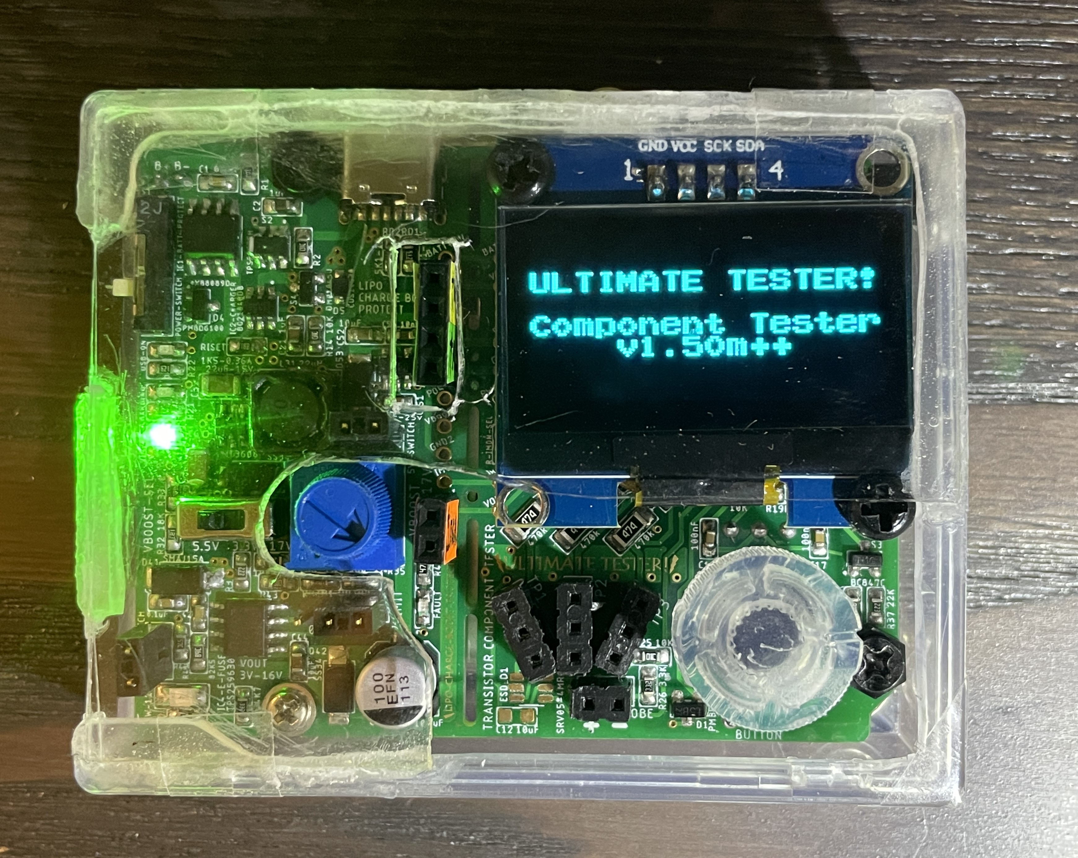
Introducing the Ultimate Tester!


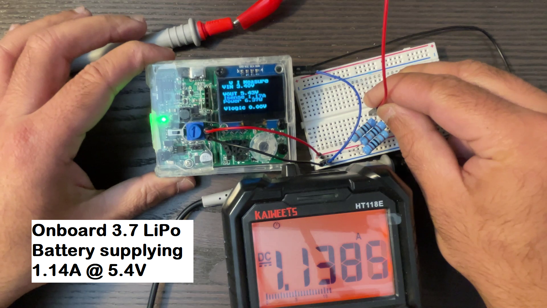
This project combines the functionality of measuring important parameters of common electronic components like Resistors, Capacitors, Inductors, Diodes, MOSFETs, Transistors, etc., and providing a Variable DC voltage source of 3-15V with upto 1.5-0.5A of current using a Lithium Polymer Battery or USB power along with an ability to measure DC Voltages upto 21V and DC Currents between +-5A. All this compressed into the form factor of an Arduino Uno! With it’s capabilities, it can serve as a quite accurate pocket sized Digital Multimeter and battery powered Power Supply.
Specifications:
- LiPo Charge Boost Protect Power (Inspired by Great Scott’s Design):
- Input: Auto-select USB-C 5V (Addition) or Single Lithium Polymer 3.7V Battery
- Battery Protection IC: XB8089D
- Battery Charging IC: BQ21040DB (Replacement)
- Boost IC: MT3608 with 22uH power inductor (Replacement)
- Output: Selectable constant 6V or variable 4.5V-15V, upto ~1.6A max at 6V
- V-out Circuit Protection: TPS259630 with UVLO 3V, OVLO 15V & Short-circuit protection, Current limits selectable at 0.5A and 1.6A, Red LED at Fault
- Output Headers:
- Vin (battery or USB-C power)
- Precise 5V-200mA max, -40mA for Component Tester
- Vout with selected voltage and current limit
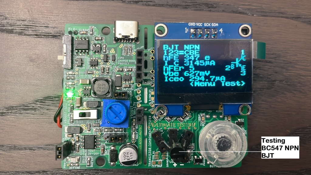
- Component Tester (OSHW Project):
- Atmega328P MCU at 20MHz
- Tests Resistors, Capacitors, Inductors, Diodes, Transistors, MOSFETS, etc
- PWM & Square Wave Generator with Frequency 0-1KHz
- Flashlight
- Logic Probe
- DC Voltage Sense upto 21V max
- DC Current Power Sense (Addition)
- Current sense +-5A using TMCS1108A4B IC

Project Github: https://github.com/pk17r/Transistortester-Warehouse/tree/prash/ComponentTester-1.50m
Project Schematics, PCB, Boost resistors and E-Fuse resistor calculations, BOM and Gerber Files: https://github.com/pk17r/Transistortester-Warehouse/blob/prash/ComponentTester-1.50m/UltimateTester_PCB.zip
Few cool things that I added:
- Auto-select between 5V USB and 3.7V Battery voltage: When USB power is available, its a good idea to use USB power instead of battery power. This lets the battery charge aptly and also allows us to use more powerful USB power. John Main has made and posted a superb way to achieve this using a P channel MOSFET.
- Load Switch to connect-disconnect battery: There are multiple ways to do this. In my older PCB I used a P channel and a N channel MOSFET similar to a way mentioned here but for this PCB I used TPS22995H-Q1, a 5.5V 3A Load Switch. I found that the enable pin gets stuck at enable as MCU is unable to fully drain it. Therefore, I added a pull-down resistor in board re-work and updated schematics with the correction.
- Electronic Fuse: TPS259630, similar to what Great Scott used but a different version with Under Voltage Lock Out, Over Voltage Lock Out, independent current limit and Latch Off. I also added a Fault LED, just to make faults fun and visible.
- Bidirectional current sensing using TMCS1108A4B IC, +-5A.
This year while working on one project where I needed to experimentally find best suitable resistor value, it was becoming tedious to keep measuring resistor values using a multimeter. I wanted a small tester that could measure resistor values and just display it. For my use I jumbled together a small circuit that could measure resistor values approximately using a potential divider on an Arduino Uno and a display. But then I came across this Open Source Hardware Project called Transistor Tester1 and Component Tester2 that could almost very accurately measure resistances as well as a bunch of other components as well. The Transistor Tester project was made by Karl-Heinz and Component Tester is an off-shoot of the main project, maintained by Markus Reschke, which is updated regularly and has more functionality. I am using the Component Tester project. The documentations and support of the project is phenomenal and many people world over have built their own component testers using these projects.
Besides testing components, one always need a voltage source while making circuits and having a small independent voltage source makes working far easier and the work desk cleaner. Along with the voltage source, having the ability to measure current and voltages without a multimeter is very useful. While building one myself, I came across the Lithium Polymer Battery Charge Boost Protect Circuit by Great Scott3 (YouTube) (SparkFun) and absolutely wanted it. One thing I wanted to change was have it in an even small size and with USB auto select function. I couldn’t find any license on SparkFun or Elector website. I have put this project as an Open Source Hardware Project.
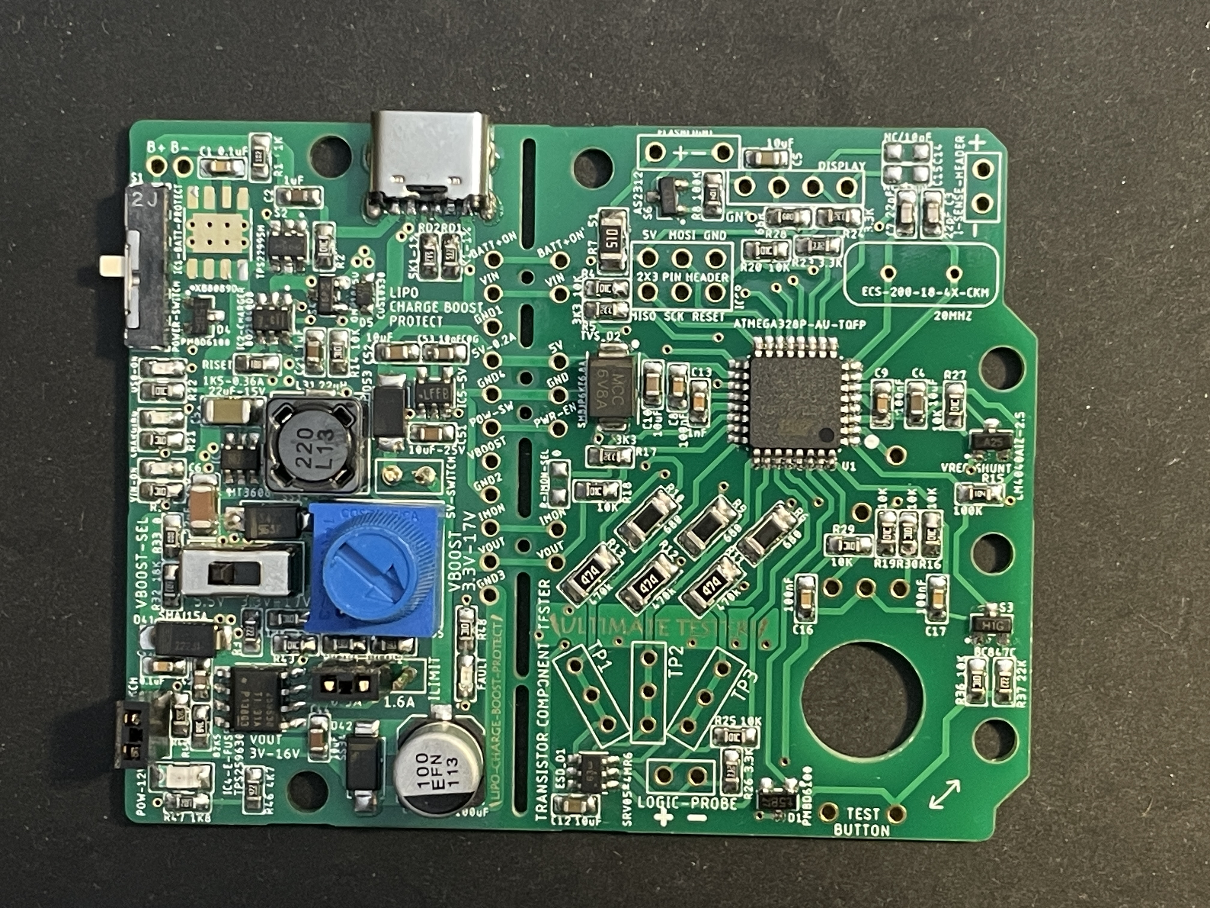
The Component Tester project uses a 9V battery and there are many testers on popular e-commerce websites based on this project. I found the testers on the market to be bulky and I wanted something small. Therefore, I set out to make my own using a small 3.7V Lithium Polymer battery. This was a great opportunity to expand my electronics knowledge and design a cool functionality packed PCB. To keep the PCB clean, I divided it into 2 parts – LiPo Charge Boost Protect Circuit and Component Tester Circuit. I took Arduino Uno’s PCB as the dimensions and fit everything inside there, creating a one sided PCB, which can be broken, if needed, to separate the two parts as well. I also added a voltage, current and power functionality as well. The board us able to generate 1.5A at 6V on capable USB voltage supply. I have chosen a 1100mAh battery for this project, using which I am able to get 1.2A current at 6V for short times. Sustained current should be around 0.5-0.6A at 6V.
Demonstration video:
This was my third PCB for the project. My first one had small mistakes that made it not work. Second one works but does not have Variable Voltage Source or Current measure and again had a minor mistake. For the third one, I tried to take my time and test as much of the circuit as possible on a breadboard before making it. Even then there were some components which were not tested. I needed to make manual corrections of adding a pull-down resistor R38 on S2 Load Switch’s enable pin and directly connected E-Fuse with 5V line instead of powering it using ATMEGA328P. I also removed monitoring option of current through E-Fuse as IMON here is very inaccurate at under 100-150mA as mentioned in the datasheet. On this PCB I am using TMCS1108A4B as the current sensor which is quite accurate above 10mA of current. In the first PCB I had put ground planes on both top and bottom layers, but later found that it is not really necessary unless there are high speed lines involved, and did not put top layer ground plane on this PCB. Making it one-sided (except the current sense IC) makes soldering much easier. I got my PCB made from JLCPCB and got a stencil made as well. I used a $15 55x55mm2 hot plate called MHP30, bought from AliExpress, that works very well using USB-C PD port at 20V. I used Chip Quik NC191LTA10 Smooth Flow Low Temp Solder Paste Sn42/Bi57/Ag1 T4 10g Syringe as the solder paste. I found it to be okay to good. There were some bubbles left after soldering. It melted at around 160 deg C.
Nice boards/equipment I came across:
- Type-C USB Lithium Li-ion 18650 3.7V 4.2V Battery Charger Board DC-DC Step Up Boost Module TP4056 https://www.aliexpress.us/item/3256805102704359.html
- MHP30 Hot Plate SMD Preheater Rework Station Temperature adjustable PCB Board Soldering Desoldering Heating Plate Tool https://www.aliexpress.us/item/3256805699007088.html
- MT3608 DC-DC Step Up Boost Power Converter 2A Module Adjustable Step Up Voltage Regulator Board Voltage 2-24V to 5V-28V Output Voltage https://www.amazon.com/gp/product/B0C8D658R7
Shortcomings and Possible Improvements:
- Separate Boost Power Source for Component Tester circuit:
In the designed board, Component Tester circuit is powered from VOUT of LiPo Charge Boost Protect circuit. The 5V LDO needs VOUT to be 6V and above for full 200mA of 5V power. Component Tester circuit with FlashLight Off requires around 35mA of current at 5V. The LDO can generate this when VOUT is at least 5.30V. Therefore, VOUT is constrained to be at least above 5.3V for Component Tester circuit to work properly. When 5V output goes down, ADC readings of ATMEGA and Hall Effect Current Sensor IC become inaccurate. This can be rectified by adding another boost circuit directly powered from VIN, producing 6V and 5V LDO’s input being transferred to this 6V source. Doing this will separate VOUT from Component Tester circuit. - Current sensor IC can be moved to LiPo Charge Boost Circuit and connected in between VOUT and VOUT Header. This will directly let Current Sense IC to measure VOUT current.
- Hall Effect Current Sense IC is not very accurate in measuring small mA currents. Instead of this IC, INA226 can be used. INA226 will send measured current to ATMEGA using I2C instead converting current to voltage. This will remove inaccuracy caused in measuring voltage at ATMEGA ADC as well as let VOUT drop to below 5V at higher current loads as INA226 works at 3-5.5V power. Though using INA226 will require its I2C setup, calibrate and read functions to be written in C as Component Tester project does not use Arduino libraries, which is quite a bit of work and testing. For this reason I choose the IC that I used here.
- Instead of using a Boost IC, a Buck Boost IC can be used: Currently a limitation created by Boost IC is VOUT is >= VIN. Using a Buck Boost IC, VOUT can go lower than VIN.
References:
- Transistor Tester Project https://www.mikrocontroller.net/articles/AVR_Transistortester ↩︎
- Component Tester Project https://github.com/madires/Transistortester-Warehouse ↩︎
- Lithium Polymer Battery Charge Boost Protect Circuit by Great Scott https://www.youtube.com/watch?v=6LxRnf6sQNQ&ab_channel=GreatScott%21 https://www.sparkfun.com/products/18004 ↩︎
